Introduction: While
parking the car the driver should be more careful because he cannot see
the back of the car while parking or taking reverse, if there is any
obstacle and ran over it might be get damage to the car. Our project
will help the person in the driving seat and give alarm if there is any
obstacle or a wall while parking or while driving in reverse.
Block Diagram of Car Parking Guard:
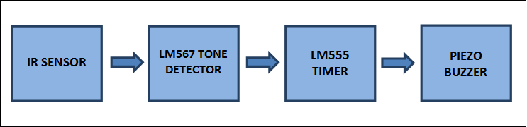
The IR sensor will detect the obstacle
with in 100cm, if there is any obstacle it will sense and give
information to the tone detector which will enable the LM555 timer to
generate a PWM for the buzzer. The LM555 will generate the pulse which
helps to buzz the buzzer so driver can understand that there is an
obstacle.
Main Component Explanation:
LM567: is a tone
detector which can interpret the frequency generated by the other
component and give the output according to the application designed by
the engineer. For example if a component is attached to the input of
LM567 which can generate a 40 kHz signal , but we to function the
following circuit when the component has reached to the 40KHz. At this
decision making we will use tone detector. The tone detector is mainly
used in touch tone decoders, ultrasonic controls, frequency monitoring
and control etc.
LM555: is a timer which
can generate a PWM signals in various width and duty cycles. The 555
timer is mainly used to control the other peripherals like motors,
detectors, regulators etc.
IR Sensor: the main
function of the IR sensor is to produce a beam for certain distance (the
distance of the beam is always depends on the IR sensor, different IR
sensor have different range of beam distance) if the there is any
obstacle in the beam it will conduct and give signal.
Photo Darlington Transistor:
the photo darlington transistor will act as a photo detectors. They
will conduct to the light or electro magnetic signals. The main function
of this transistor is to amplify the input signal of the transistor.
But it will work slowly when compared to the other transistors. It is
having a maximum frequency of 20 KHz.
Circuit Diagram of Car Parking Guard: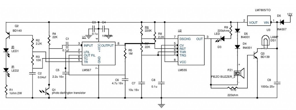 Explanation:
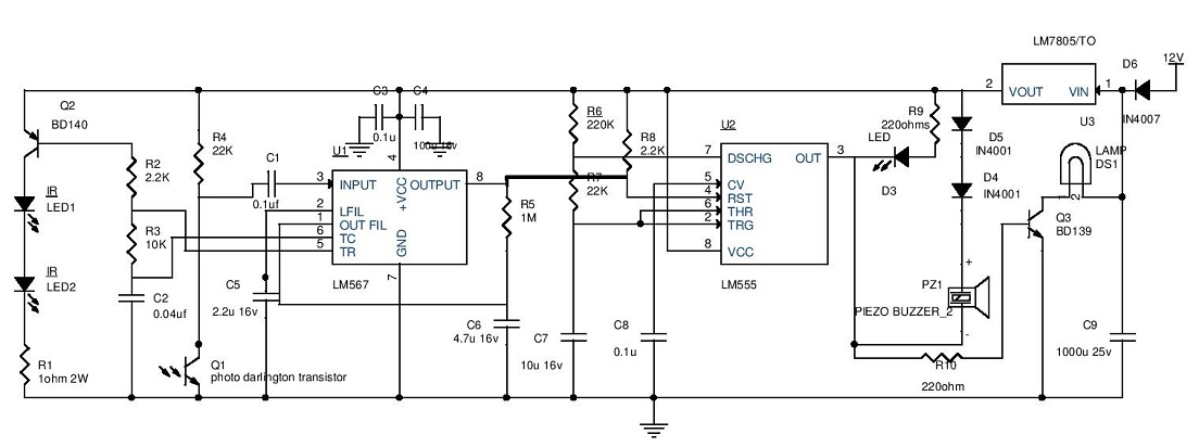
- The reverse indicator light supply is given to the 7805 regulator to give 5v to the rest of the circuit. The diode D6 is used to eliminate the reverse current and wrong supply polarity.
- When the car is driving in reverse the car battery will provide DC supply the reverse light indicator at the back of the car when this supply came to the reverse light indicator the circuit will have the power supply.7805 will regulate the DC voltage to 5V and give to the IR Sensors through the transistor with 20 KHz modulating frequency of the LM567 (TONE DETECTOR) available at Pin5. The resistor R1 will resists the IR senor current. At this point the pin8 of LM567 is high which will enable the LM555 timer operating in astable multivibrator mode. The output of the timer is enabled which can be assured by the LED (blinking) and also buzzer will beeps at determined rate given by the resistors R6, R7 and capacitor C7. The timer output also is given to the lamp through a transistor. The lamp will blink as a warning signal because of the PWM signal generated by the timer, transistor will work as a switch and resistor R10 will limit the current. This condition is maintained until the 20 KHz signal is received by the pin3 of the LM567.
- The above condition is when there is no obstacle in the path of the car while taking reverse. If there is a obstacle the IR beam will radiate back to the IR sensor and the 20KHz modulated signal is given to the pin3 of LM567 through photo Darlington transistor, at this point the pin8 of the LM567 is turned to low and also gets locked to detect the 20Khz signal. By this the LM555 is turned low and disabled by this the led will remain lighting and buzzer makes the continuous sound to alert the driver.
Note: This complete circuitry
will be attached to the back bumper and placed at the center. The buzzer
and led should be placed on the dash board for visibility of light and
hearing purpose for the driver.
Make the connection to the reverse indicator light and the circuit in parallel and beware of the polarity.
Comments