
Metal Detector Circuit


Introduction:
Metal detector is very common devices for checking the person in shopping malls, hotels, cinema halls to ensure that person is not carrying any explosive metals or illegal things like guns, bombs etc. metal detectors can be created easily and the circuit is not that complex.

Block Diagram of Metal Detector:

Metal Detector - Block Diagram
The LC circuit is nothing but inductor and capacitor which is connecter in parallel. The LC circuit will trigger the proximity sensor if it detects any metal near to it. Proximity sensor will give glow the led, and also make the buzz with the help of the buzzer.


Main Components in Metal Detector Circuit:

LC CIRCUIT: LC Circuit is a resonating circuit which will resonate when exact same frequency material comes near. The LC circuit consist of inductor and capacitor connected in parallel , when the capacitor is fully charged the charge of the capacitor will be given to the inductor, here inductor will have improve its magnetic field. After some time the capacitor will have no charge and current from the inductor will be given to the capacitor in a reverse polarity and capacitor will get charge and now the inductor magnetic field and current will become nil. Again charged capacitor will give current to the inductor to improve its magnetic field. Note inductor is a magnetic field storage device and capacitor is electric field storage device.

PROXIMTY SENSOR: The proximity sensor can detect the objects with out any physical interference. The proximity sensor will work same as infrared sensor, proximity also release a signal, it will not give output unless and until there is no change in the reflected back signal, If there is a change in signal it will detect and give the output accordingly. There are different proximity sensors for example to detect plastic material we can use capacitive type proximity and for metals we should use inductive type.

Circuit Diagram of Metal Detector:

Metal Detector - Circuit Diagram

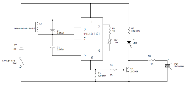
Metal Detector Circuit Explanation:

  • When the LC circuit that is L1 and C1 has got any resonating frequency from any metal which is near to it, electric field will be created which will lead to induces current in the coil and changes in the signal flow through the coil.
  • Variable resistor is used to change the proximity sensor value equal to the LC circuit, it is better to check the value when there is coil not near to the metal. When the metal is detected the LC circuit will have changed signal. The changed signal is given to the proximity detector (TDA 0161), which will detect the change in the signal and react accordingly. The output of the proximity sensor will be of 1mA when there is no metal detected and it will be around 10mA when coil is near to the metal
  • When the output pin is high the resistor R3 will provide positive voltage to transistor Q1. Q1 will be turned on and led will glow and buzzer will give the buzz. Resistor r2 is used to limit the current flow.

Comments

Popular posts from this blog

LED DIMMER WITH CIRCUIT DIAGRAM

In this circuit, at the starting LED glow slowly, then grown brighter and once again slowly it became dim. The basis of the whole circuit is an operational amplifier IC named LM358. Circuit Diagram of LED Lamp Dimmer: LED Lamp Dimmer Circuit Diagram – ElectronicsHub.Org Working of LED Lamp Dimmer Circuit: LM358 is mainly made up of a package which contains two not dependent operational  amplifiers of high gain. The most significant attribute of these IC is that we have no need of the  independent power supply for the functioning of each comparator till the large range of the power supply. LM358 can be employed like transducer amplifier or can be worked as DC gain block etc. The huge DC voltage gain of the LM358 IC is 100db. For the only power supply this IC can work on the voltage range of 3V to 32V while for the twin power supply this IC work on the range of ±1. 5V to ±16V . And moreover large output voltage is also supported by it. Related Post: PWM LED Dimmer

WIRELESS SWITCH CIRCUIT DIAGRAM

Generally appliances that we used in our home are being controlled with the  help of devices like switches, senors. However sometimes it is dangerous to have physical contact with these switches. So to overcome these dangers, here we have explained a circuit that needs no physical contact with the appliance. In these circuits all you  need is to pass your hand  above LDR. As you first pass your hand over LDR the device connected with  it started and remain in that state till you again pass your hand above LDR. These circuits are mainly depending on two ICs. First one is LM714 which is an operational amplifier. These IC is used to increase the voltage level at the output hundred  of a thousand times as compared with  the input. Another one is most generally used JK flip flop i.e. CD4027. These IC works in toggle mode and based on the JK flip flop master slave concept. This IC is used to alter the state when the signal is given to the any one of the input terminals and

Automatic Railway Gate Controller with Circuit Diagram

The main aim of this project is to operate and control the unmanned railway gate in the proper manner in order to avoid the accidents in the unmanned railway crossing. In a country like ours where there are many unmanned railway crossings, accidents are increasing day by day. These train accidents are due to the absence of human power in the railway. In order to overcome the accidents due to the above problem we have planned to design the project. Automatic Railway Gate Control System with High Speed Alerting System is an innovative circuit which automatically controls the operation of railway gates detecting the arrival and departure of trains at the gate. It has detectors at the far away distance on the railway track which allows us to know the arrival and departure of the train. These detectors are given to microcontroller which activates the motors which open/close the railway gate correspondingly. Another feature of this circuit is that it has an intellige