
Fire Alarm Circuit

This circuit alerts us when there is a fire accident at home by ringing a siren sound. You might have seen fire alarms earlier but this is quite different as it generates a siren sound instead of a buzzer and also it uses basic components to generate that siren sound.
We are aware that there are many integrated circuits which can be used to generate the siren effect but we preferred to use basic electronics components like resistors, capacitors and transistors to generate it so that you will clearly understand the internal working of it and it will be much useful for you as you will gain more knowledge by analyzing it instead of simply going or pre designed integrated circuits.

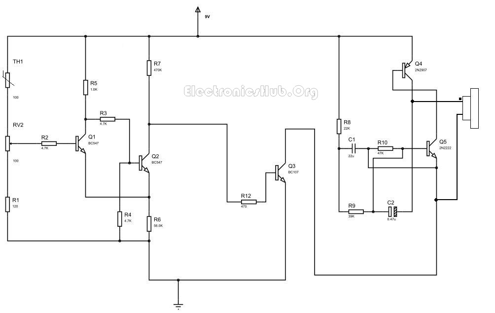
Circuit Diagram of Fire Alarm:

Fire Alarm Circuit With Siren SoundDescription:
This circuit uses a thermistor to sense the temperature. When it senses that the temperature of the environment is increasing above a given threshold, then it gives a signal. The temperature at which the circuit detects fire can be adjusted by using the potentiometer arrangement at RV2.

When the temperature increases above the set value, the potentiometer arrangement produces a high voltage. This voltage is then given to BC547 transistor in common emitter mode. It is an NPN general purpose transistor. When the  base is given a high input, it gets turned on. When the transistor is turned on, its collector voltage is reduced to low as the collector to emitter voltage decreases. The collector output voltage of the first transistor is given to the base as an input to the second BC 547 NPN transistor. This transistor too is in common emitter mode and as the input is low when the temperature threshold is reached, the output at the collector will rise high. In this state, it will turn on the next transistor, i.e BC107. This transistor will now act as a switch for the siren circuit. This transistor can bear power quite larger than the BC547 and it is also equipped with a heat sink for that purpose.
When the BC107 transistor turns on, it  allows current to pass from power supply to ground through collector thereby acting as an electronically controlled switch. When the current is passing, the siren circuit which is assembled as the load to the circuit is turned ON. Then you can hear the siren sound through the buzzer. The capacitors used in the circuit are the main components in producing the siren effect. The principle involved in generating the siren effect is to make an oscillator with an envelope which periodically increases and decreases so as to generate that effect.


contact:
 DEV HARSHA
whatsapp,hike nd calls
8978511693 & 9505630317

Comments

Popular posts from this blog

Automatic Railway Gate Controller with Circuit Diagram

The main aim of this project is to operate and control the unmanned railway gate in the proper manner in order to avoid the accidents in the unmanned railway crossing. In a country like ours where there are many unmanned railway crossings, accidents are increasing day by day. These train accidents are due to the absence of human power in the railway. In order to overcome the accidents due to the above problem we have planned to design the project. Automatic Railway Gate Control System with High Speed Alerting System is an innovative circuit which automatically controls the operation of railway gates detecting the arrival and departure of trains at the gate. It has detectors at the far away distance on the railway track which allows us to know the arrival and departure of the train. These detectors are given to microcontroller which activates the motors which open/close the railway gate correspondingly. Another feature of this circuit is that it has an intellige...

LED DIMMER WITH CIRCUIT DIAGRAM

In this circuit, at the starting LED glow slowly, then grown brighter and once again slowly it became dim. The basis of the whole circuit is an operational amplifier IC named LM358. Circuit Diagram of LED Lamp Dimmer: LED Lamp Dimmer Circuit Diagram – ElectronicsHub.Org Working of LED Lamp Dimmer Circuit: LM358 is mainly made up of a package which contains two not dependent operational  amplifiers of high gain. The most significant attribute of these IC is that we have no need of the  independent power supply for the functioning of each comparator till the large range of the power supply. LM358 can be employed like transducer amplifier or can be worked as DC gain block etc. The huge DC voltage gain of the LM358 IC is 100db. For the only power supply this IC can work on the voltage range of 3V to 32V while for the twin power supply this IC work on the range of ±1. 5V to ±16V . And moreover large output voltage is also supported by it. Related Post: PWM L...

Automatic Street Light Controller Circuit Using Relays and LDR

Summary: Did you ever think that how the street lights automatically turn ON in the night and turn OFF automatically at morning? Is there any person who comes to ON/OFF these lights? The following circuit that described below which perform this job automatically. This circuit employed the output from an uncomplicated light/dark activated circuit and oblige a relay in its output which can be further attached to switch ON/OFF a street light and electrical application in a household also. Many of the people have a phobia of darkness, so to assist them in such situation, we have explained a simple circuit . It will automatically turn on street light in the way of LED’s or bulb coupled with relay, it is well enough to see the object nearby. This circuit is very much easy to work and also the battery power consumed by the circuit is very low because of the very few components used in the circuit. Also Read the Interesting Post: Automatic Plant Watering Syste...